
Related Topics
Set up a VPN Between Two Fireware Devices (WSM)
A branch office virtual private network (BOVPN) tunnel is a secure way for networks, or for a host and a network, to exchange data across the Internet. This document tells you how to use Policy Manager to define a manual BOVPN tunnel between two Fireboxes that use Fireware v11.x or higher.
For the same example as configured in Fireware Web UI, see Set up a VPN Between Two Fireware Devices (Web UI).
This topic does not give detailed information about the different settings in the BOVPN dialog boxes or how they affect an existing tunnel. If you want to know more about a particular setting, see:
Collect IP Address and Tunnel Settings
To create a manual BOVPN tunnel, you must first collect the IP addresses and determine the settings for the endpoints. You might find it helpful to print out this document, write down or indicate the values you want to use, and refer to them when you configure the settings in Policy Manager.
For this topic, both endpoints must have static external IP addresses.
For information on BOVPN tunnels to devices with a dynamic external IP address, see Define Gateway Endpoints for a BOVPN Gateway.
If you are the administrator of only one of the two devices, you can give the table to the other administrator to make sure he or she uses exactly the same values for the Phase 1 and Phase 2 settings.
Make sure that you configure the VPN endpoints correctly and that the Phase 1 and Phase 2 settings are the same on both devices. Tunnels do not build if the settings do not match.
If a setting does not appear in this list, do not change the default value.
BOVPN Tunnel Settings
SITE A (Firebox with Fireware Fireware v11.x or higher)
Public IP address: ______________________________
Private IP address: _____________________________
SITE B (Firebox with Fireware Fireware v11.x or higher)
Public IP address: ______________________________
Private IP address: _____________________________
PHASE 1 Settings (Both Sides Must Use Exactly the Same Values)
For a BOVPN tunnel between two Fireboxes that use Fireware, we recommend that you select Dead Peer Detection (RFC3706), not IKE Keep-Alive. Do not select both. You should always select Dead Peer Detection if both endpoint devices support it.
Credential method: Select Use Pre-Shared Key.
Pre-shared key: ______________________________
IKE Version: IKEv1 ____ IKEv2 ____ (requires Fireware v11.11.2 or higher)
Mode (choose one): Main ____ Aggressive ____
NAT Traversal: Yes ____ No ____
NAT Traversal Keep-alive interval: ________________
IKE Keep-alive: Yes ____ No ____
IKE Keep-alive Message interval: ________________
IKE Keep-alive Max failures: ________________
Dead Peer Detection (RFC3706): Yes ____ No ____
Dead Peer Detection Traffic idle timeout: ________________
Dead Peer Detection Max retries: ________________
Authentication algorithm (choose one): MD5___SHA1____ SHA2-256____SHA2-384____SHA2-512_____ (We recommend SHA-1 or SHA-2)
Encryption algorithm (choose one): DES____ 3DES____ AES-128____ AES-192____ AES-256____ (We recommend AES-128, AES-192, or AES-256)
SA Life ________________
Select Hours as the unit for SA life.
Diffie-Hellman Group (choose one): 1____ 2____ 5____14____15____19____20____
PHASE 2 Settings (Both Sides Must Use Exactly the Same Values)
Perfect Forward Secrecy (Diffie-Hellman Group): Disable____ Group1____ Group2____ Group5____ Group14____ Group15____ Group19____ Group20____
Authentication algorithm (choose one): MD5____ SHA1____ (We recommend SHA-1)
Encryption algorithm (choose one): DES____ 3DES____AES____ (We recommend AES. The encryption strength for this AES setting is 256-bit.)
Force Key Expiration Time (Hours): ________________
Force Key Expiration Traffic (kilobytes): ________________
Example Tunnel Settings
This section has the same fields as the previous section, and includes example settings. These settings correspond to the settings that appear in the images in this example.
SITE A (Firebox with Fireware v11.x or higher)
Public IP address: 203.0.113.2
Private network IP address: 10.0.1.0/24
SITE B (Firebox with Fireware v11.x or higher)
Public IP address: 198.51.100.2
Private network IP address: 10.50.1.0/24
PHASE 1 Settings (Both sides must use exactly the same values)
Credential method: Select Use Pre-Shared Key.
Pre-shared key: SiteA2SiteB
Version: IKEv1
Mode: Main
NAT Traversal: Enable
NAT Traversal Keep-alive interval: 20 seconds
IKE Keep-alive: Disable
IKE Keep-alive Message interval: none
IKE Keep-alive Max failures: none
Dead Peer Detection (RFC3706): Enable
Dead Peer Detection Traffic idle timeout: 20 seconds
Dead Peer Detection Max retries: 5
Authentication algorithm: SHA256
Encryption algorithm: AES (256-bit)
SA Life: 24 hours
Diffie-Hellman Group: 14
PHASE 2 Settings (Both sides must use exactly the same values)
Perfect Forward Secrecy (Diffie-Hellman Group): 14
Type: ESP
Authentication algorithm: SHA256
Encryption algorithm: AES (The encryption strength for this AES setting is 256-bit.)
The settings in this example are the default Phase 1 and 2 settings in Fireware v12.0 and higher. The default Phase 1 and 2 settings are different in Fireware v11.12.4 and lower. For more information about these settings in Fireware v11.12.4 and lower, see the previous version of Fireware Help.
Configure Site A
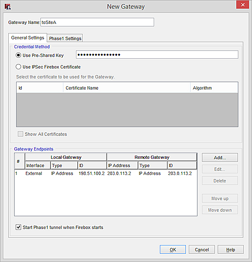
You now use Policy Manager to configure the gateway at Site A that has a Firebox with Fireware v11.x or higher. A gateway is a connection point for one or more tunnels. To configure a gateway, you must specify:
- Credential method (either pre-shared keys or an IPSec Firebox certificate)
- Location of local and remote gateway endpoints, either by IP address or domain information
- Settings for Phase 1 of the Internet Key Exchange (IKE) negotiation
Add a VPN Gateway
- Select VPN > Branch Office Gateways.
The Gateways dialog box appears. - Click Add.
The New Gateway dialog box appears.
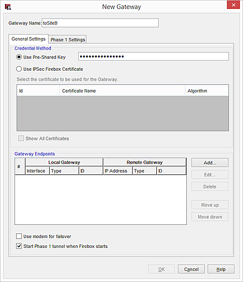
- In the Gateway Name text box, type a name to identify this gateway in Policy Manager.
- In the Credential Method area, select Use Pre-Shared Key. Type the shared key.
The shared key must use only standard ASCII characters. - In the Gateway Endpoints section, click Add.
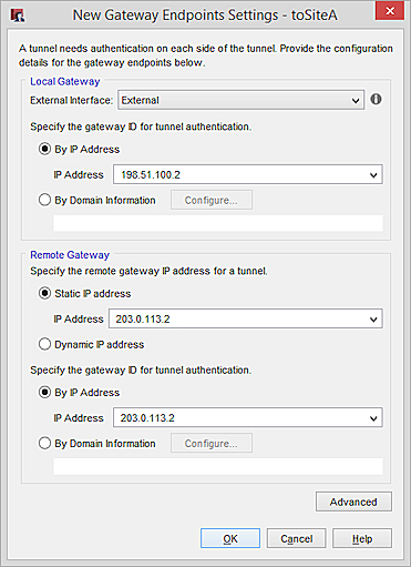
The New Gateway Endpoints Settings dialog box appears.
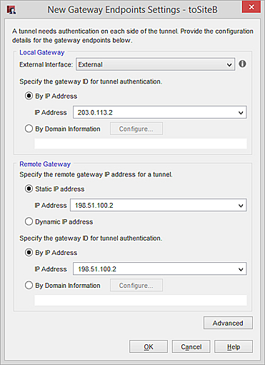
- From the External Interface drop-down list, select the interface that has the external (public) IP of the Site A Firebox.
- In the Local Gateway section, select By IP Address.
- From the IP Address drop-down list, select the external (public) IP address for the Site A Firebox . All configured interface IP addresses appear in the list.
- In the Remote Gateway section, for Specify the remote gateway IP address for a tunnel, select Static IP Address.
- In the IP Address text box, enter the external (public) IP of the Site B Firebox.
- To specify the gateway ID, select By IP Address.
- For IP Address, enter the external (public) IP of the Site B Firebox.
- Click OK to close the New Gateway Endpoints Settings dialog box.
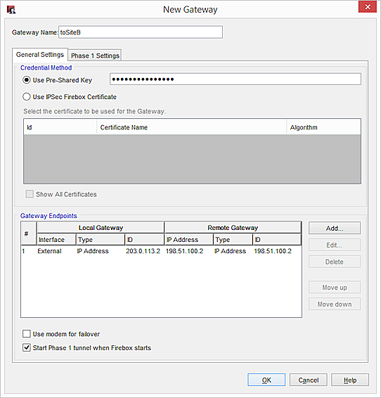
The gateway pair you defined appears in the list of gateway endpoints.
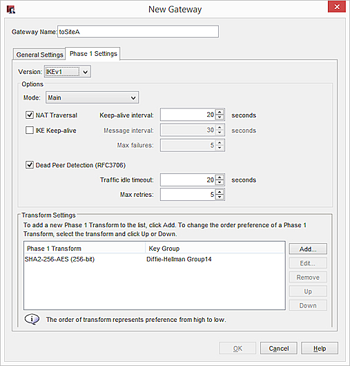
Configure the Phase 1 Settings
Phase 1 of establishing an IPSec connection is where the two peers make a secure, authenticated channel they can use to communicate. This is known as the ISAKMP Security Association (SA).
- Select the Phase 1 Settings tab.
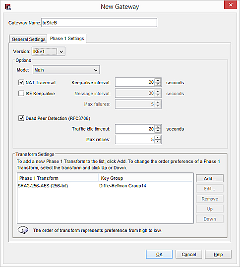
- From the Mode drop-down list, select Main.
The example uses Main Mode because both endpoints have static IP addresses. If one endpoint has a dynamic IP address, you must use Aggressive mode. - Select NAT Traversal and Dead Peer Detection (RFC3706). These are the recommended settings for a BOVPN tunnel between two Fireboxes.
- In the Transform Settings area, select the default transform and click Edit.
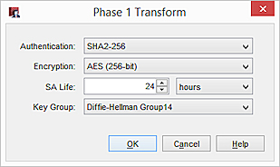
- From the Authentication and Encryption drop-down lists, select your preferred algorithm. In our example, we use SHA256 and AES (256-bit).
- In the SA Life text box, type 24 and select Hours.
- From the Key Group drop-down list, select a Diffie-Hellman group. In our example, we select Diffie-Hellman Group 14.
- Click OK. Leave all other Phase 1 settings with their default values.
- Click OK to close the New Gateway dialog box.
The gateway you added appears in the Gateways list.
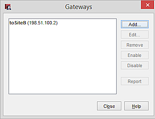
- Click Close to close the Gateways dialog box.
Add a VPN Tunnel
After you define gateways, you can make tunnels between them. The process for making a tunnel includes:
- Specify routes (local and remote endpoints for the tunnel)
- Configure Phase 2 of the Internet Key Exchange (IKE) negotiation
From Policy Manager:
- Select VPN > Branch Office Tunnels.
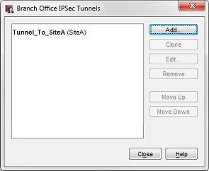
The Branch Office IPSec Tunnels dialog box appears. - Click Add.
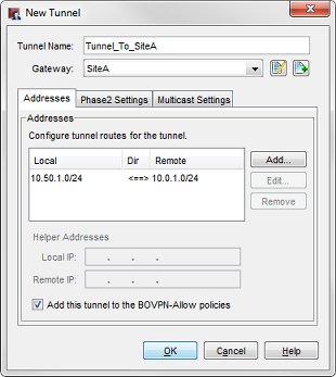
The New Tunnel dialog box appears.
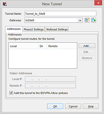
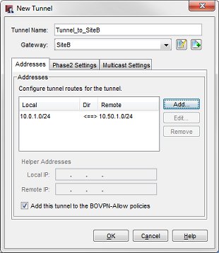
- In the Tunnel Name text box, type a name for the tunnel.
- From the Gateway drop-down list, select the gateway you just created.
- Select the Add this tunnel to the BOVPN-Allow policies check box at the bottom of the dialog box if you want to add the tunnel to the BOVPN-Allow.in and BOVPN-Allow.out policies. These policies allow all traffic that matches the tunnel routes. If you want to restrict traffic through the tunnel, clear this check box and use the BOVPN Policy Wizard to create policies for types of traffic that you want to allow through the tunnel. For more information, see Define Custom Tunnel Policies.
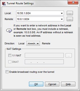
- In the Addresses area, click Add.
The Tunnel Route Settings dialog box appears.
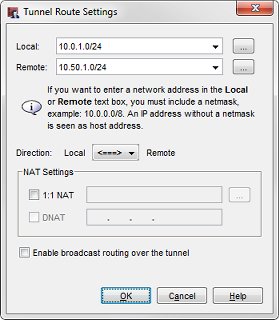
- In the Local text box, type the local (private) network address for Site A. You can also click the button adjacent to the Local drop-down list to enter a host IP address, network address, range of host IP addresses, or DNS name. These are the devices behind the local Firebox that will be able to communicate through the tunnel.
- In the Remote text box, type the remote (private) network address. This is the Site B private network IP address. You can also click the adjacent button to enter a host IP address, network address, range of host IP addresses, or DNS name. These are the devices behind the remote Firebox that will be able to communicate through the tunnel.
- From the Direction drop-down list, click the tunnel direction. The tunnel direction determines which endpoint of the VPN tunnel can start a VPN connection through the tunnel.
- Click OK.
The tunnel route appears in the Addresses tab of the New Tunnel dialog.
Configure the Phase 2 Settings
Phase 2 settings include settings for a security association (SA), which defines how data packets are secured when they are passed between two endpoints. The SA keeps all information necessary for the Firebox to know what it should do with the traffic between the endpoints.
- From the New Tunnel dialog box, select the Phase 2 Settings tab.
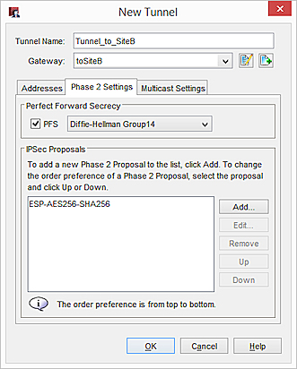
- Select the PFS check box to enable Perfect Forward Secrecy (PFS).
- Select a Diffie-Hellman Group from the drop-down list. In our example, we select Diffie-Helman Group 14.
- The Firebox contains one default proposal, which appears in the IPSec Proposals list. This proposal specifies the ESP data protection method, AES 256-bit encryption, and SHA256 authentication. For this example, we use the default proposal. You can either:
- Use the default proposal.
- Remove the default proposal. Then select a different proposal in the drop-down list and click Add.
- Add an additional proposal, as described in Add a Phase 2 Proposal.
- Click OK to return to the Branch Office IPSec Tunnel dialog box.
The tunnel you added appears on the Branch Office IPSec Tunnels list.
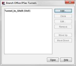
- Click Close and save the changes to the Firebox.
The Firebox at Site A is now configured.
Configure Site B
You now use Policy Manager to configure the gateway at Site B that has an Firebox with Fireware 11.x or higher.
Add a VPN Gateway
- Select VPN > Branch Office Gateways.
The Gateways dialog box appears. - Click Add.
The New Gateway dialog box appears. - In the Gateway Name text box, type a name to identify this gateway in Policy Manager.
- Click the General Settings tab.
- In the Credential Method area, select Use Pre-Shared Key. Type the shared key.
This shared key must use only standard ASCII characters. - In the Gateway Endpoints section, click Add.
The New Gateway Endpoints Settings dialog box appears.
- In the External Interfacedrop-down list, select the interface that has the external (public) IP of the Site B Firebox.
- Select By IP Address.
- From the IP Address drop-down list, select the external (public) IP address for the Site B Firebox . All configured interface IP addresses appear in the list.
- To specify the gateway IP address, select Static IP Address. Type the external (public) IP address of the Site A Firebox.
- To specify the gateway ID, select By IP Address. Type the external (public) IP address of the Site A Firebox.
- Click OK to close the New Gateway Endpoints Settings dialog box.
The gateway pair you defined appears in the list of gateway endpoints.
Configure the Phase 1 Settings
Phase 1 of establishing an IPSec connection is where the two peers make a secure, authenticated channel they can use to communicate. This is known as the ISAKMP Security Association (SA).
- Select the Phase 1 Settings tab.
- From the Mode drop-down list, select Main.
The example uses Main Mode because both endpoints have static IP addresses. If one endpoint has a dynamic IP address, you must use Aggressive mode. - Select NAT Traversal and Dead Peer Detection (RFC3706). These are the recommended settings for a BOVPN tunnel between Fireboxes that use Fireware v11.x or higher.
- In the Transform Settings section, select the default transform and click Edit.
- From the Authentication and Encryption drop-down lists, select your preferred algorithms. In our example, we select SHA2-256 and AES (256-bit).
- In the SA Life text box, type 24. In the drop-down list, select Hours.
- In the Key Group drop-down list, select a Diffie-Helman Group. In our example, we select Diffie-Hellman Group 14.
- Click OK. Leave all other Phase 1 settings with their default values.
- Click OK. Keep the default values for all other Phase 1 settings.
- Click Close to close the Gateways dialog box.
The gateway you added appears on the Branch Office VPN page in the Gateways list.
Add a VPN Tunnel
After you define gateways, you can make tunnels between them. When you make a tunnel you must specify:
- Routes (local and remote endpoints for the tunnel)
- Settings for Phase 2 of the Internet Key Exchange (IKE) negotiation
To add a VPN tunnel:
- Select VPN > Branch Office Tunnels.
The Branch Office IPSec Tunnels dialog box appears. - Click Add.
The New Tunnel dialog box appears. - In the Tunnel Name text box, type a name for the tunnel.
- From the Gateway drop-down list, select the gateway you created.
- To add the tunnel to the BOVPN-Allow.in and BOVPN-Allow.out policies, select the Add this tunnel to the BOVPN-Allow policies check box. These policies allow all traffic that matches the tunnel routes. If you want to restrict traffic through the tunnel, clear this check box and use the BOVPN Policy Wizard to create policies for types of traffic that you want to allow through the tunnel.
- In the Addresses area, click Add.
The Tunnel Route Settings dialog box appears.
- In the Local text box, type or select the local (private) network address for Site B. You can also click the button adjacent to the Local drop-down list to enter a host IP address, network address, range of host IP addresses, or DNS name. These are the devices behind the local Firebox that will be able to communicate through the tunnel.
- In the Remote text box, type the remote private network address. This is the Site B private network IP address. You can also click the adjacent button to enter a host IP address, network address, range of host IP addresses, or DNS name. These are the devices behind the remote Firebox that will be able to communicate through the tunnel.
- From the Direction drop-down list, click the tunnel direction. The tunnel direction determines which endpoint of the VPN tunnel can start a connection through the BOVPN tunnel.
- Click OK.
The tunnel route appears in the Addresses tab of the New Tunnel dialog.
Configure the Phase 2 Settings
Phase 2 settings include settings for a security association (SA), which defines how data packets are secured when they are passed between two endpoints. The SA keeps all information necessary for the Firebox to know what it should do with the traffic between the endpoints.
- From the New Tunnel dialog box, click the Phase 2 Settings tab.

- Select the PFS check box to enable Perfect Forward Secrecy (PFS).
- If you enable PFS, in the Enable Perfect Forward Secrecy drop-down list, select a Diffie-Hellman group. In our example, we select Diffie-Hellman Group 14.
- The Firebox contains one default proposal, which appears in the IPSec Proposals list. This proposal specifies the ESP data protection method, AES 256-bit encryption, and SHA256 authentication. For this example, we use the default proposal. You can either:
- Use the default proposal.
- Remove the default proposal. Then select a different proposal in the drop-down list and click Add.
- Add an additional proposal, as described in Add a Phase 2 Proposal.
- Click OK to return to the Branch Office IPSec Tunnel dialog box.
The tunnel you added appears on the Branch Office IPSec Tunnels list.
- Click Close and save the changes to your Firebox.
The Firebox at Site B is now configured.
After both ends of the tunnel are configured, the tunnel opens and traffic passes through the tunnel. If the tunnel does not work, examine the log files on both Fireboxes for the time period you tried to start the tunnel. Log messages appear in the log file to indicate where the failure is located in the configuration and which settings might be part of the problem. You can also review the log messages in real-time with Firebox System Manager.