Configure Outgoing Dynamic NAT Through a Branch Office VPN Tunnel
You can use dynamic NAT (DNAT) through Branch Office VPN (BOVPN) tunnels. Dynamic NAT acts as unidirectional NAT, and keeps the VPN tunnel open in one direction only. This can be helpful when you make a BOVPN tunnel to a remote site where all VPN traffic comes from one public IP address.
For example, suppose you want to create a BOVPN tunnel to a business partner so you can get access to their database server, but you do not want this company to get access to any of your resources. Your business partner wants to allow you access, but only from a single IP address so they can monitor the connection.
You must know the external and trusted network IP addresses of each VPN endpoint to complete this procedure. If you enable dynamic NAT though a BOVPN tunnel, you cannot use the VPN failover feature for that VPN tunnel.
The step-by-step instructions below work with any BOVPN that uses dynamic NAT to make all traffic from one endpoint appear to come from a single IP address. The DNAT address can be any routable IP address, such as the Site A public IP address, or a private IP address on the trusted network at Site A.
Site A
Public IP address — 203.0.113.2
Trusted Network — 10.0.1.0/24
Site B
Public IP address — 198.51.100.2
Trusted Network — 10.50.1.0/24
In Fireware v12.4 or higher, if you select IPv6 Addresses as the Address Family, you cannot configure NAT. NAT is not supported for IPv6 BOVPN gateways.
Configure the Endpoint Where All Traffic Must Appear to Come from a Single Address (Site A)
For the device at Site A, configure the BOVPN gateway. For more information, go to Configure Manual BOVPN Gateways. Then use the steps below to configure dynamic NAT in the tunnel route settings.
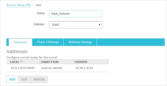
- Select VPN > Branch Office VPN.
- Click Add below to the Tunnels list to add a new tunnel, or select a tunnel and click Edit.
The Tunnel configuration settings appear. - Select the gateway from the Gateway drop-down list.
- On the Addresses tab, click Add.
The Tunnel Route Settings dialog box opens.

- In the Local IP section, select the type of local address from the Choose Type drop-down list. Then type the value in the text box below. You can type a host IP address, network address, a range of host IP addresses, or a DNS name.
- In the Remote IP section, select the type of remote address from the Choose Type drop-down list. Then type the value in the text box below. You can type a host IP address, network address, a range of host IP addresses, or a DNS name.
- In the Direction drop-down list, select local-to-remote.
You must set the direction for traffic through the tunnel before you can enable dynamic NAT for the tunnel.
- Click the NAT tab. Select the Dynamic NAT check box. In the adjacent text box, type the IP address that you want the remote network to see as the source for all traffic through the tunnel.

- Click OK.
The tunnel route is added.
- Save the changes to the Firebox.
- Select VPN > Branch Office Tunnels.
- Click Add to add a new tunnel, or select a tunnel and click Edit.
The Add Tunnel or Edit Tunnel dialog box appears. - Select the gateway from the Gateway drop-down list.
- On the Addresses tab, click Add.
The Tunnel Route Settings dialog box opens.
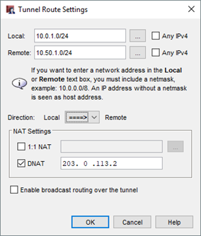
- From the Local drop-down list, select the local address you want.
You can also click the button adjacent to the Local drop-down list to specify a host IP address, network address, a range of host IP addresses, or a DNS name. - In the Remote box, type the remote network address.
You can also click the adjacent button to specify a host IP address, network address, a range of host IP addresses, or a DNS name. - From the Direction drop-down list, select the second option where the arrow points to Remote.
- Select the DNAT check box. In the adjacent text box, type the IP address that you want the remote network to see as the source for all traffic through the tunnel.
- Click OK.
The tunnel route is added.

- Save the changes to the Firebox.
Configure the Endpoint that Expects All Traffic to Come from a Single IP Address (Site B)
For the device at Site B, configure the BOVPN gateway. For more information, go to Configure Manual BOVPN Gateways. Then use the steps below to configure dynamic NAT in the tunnel route settings.
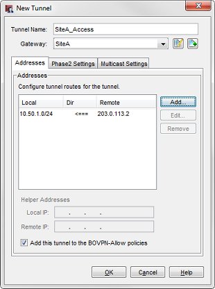
- Select VPN > BOVPN. Click Add below the Tunnels list to add a new tunnel or select an existing tunnel and click Edit.
The tunnel settings appear. - Select the gateway from the Gateways drop-down list.
- On the Addresses tab, click Add.
The Tunnel Route Settings dialog box opens.
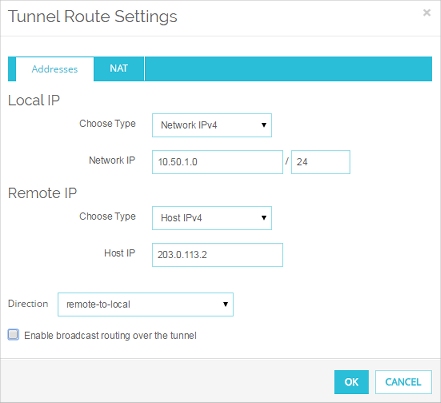
- In the Local IP section, select the type of local address from the Choose Type drop-down list. Then type the value in the adjacent text box. You can type a host IP address, network address, a range of host IP addresses, or a host name. This must match the Remote address configured in the tunnel route at Site A.
- In the Remote IP section, select the type of remote address from the Choose Type drop-down list. Type the value in the adjacent text box. You can type a host IP address, network address, a range of host IP addresses, or a host name. This must match the DNAT address configured at Site A.
- From the Direction drop-down list, select remote-to-local.
- Do not select anything in the NAT tab.
- Click OK.
The tunnel route is added.
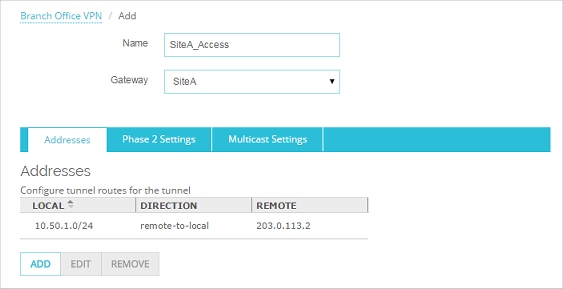
- Save the changes to the Firebox.
- From Policy Manager, configure the gateway for the BOVPN. For more information, go to Configure Manual BOVPN Gateways.
- Select VPN > Branch Office Tunnels. Click Add to add a new tunnel or select an existing tunnel and click Edit.
The Add Tunnel or Edit Tunnel dialog box opens. - Select the gateway from the Gateways drop-down list.
- On the Addresses tab, click Add.
The Tunnel Route Settings dialog box opens.

- From the Local drop-down list, select the local address you want.
You can also click the button adjacent to the Local drop-down list to specify a host IP address, network address, a range of host IP addresses, or a host name. This must match the Remote address configured in the tunnel route at Site A. - In the Remote text box, type the remote IP address. You can also click the adjacent button to specify a host IP address, network address, a range of host IP addresses, or a host name. This must match the DNAT address configured at Site A.
- From the Direction drop-down list, select the third option where the arrow points to Local.
- Do not select anything in the NAT Settings area.
- Click OK.
The tunnel route is added.
- Save the changes to the Firebox.
When the device at Site B restarts, the two devices negotiate a VPN tunnel. The Site A device applies dynamic NAT to all traffic sent to the trusted network of the Site B device. When this traffic reaches Site B, it arrives as traffic that originated from the DNAT IP address.