BOVPN Virtual Interface with SD-WAN Routing
In this configuration example, a company has two sites connected by BOVPN virtual interface tunnels. Site A has one external network connection. Site B has two external network connections with different latency. This company wants to use SD-WAN to send latency-sensitive traffic, such as VoIP traffic, through the lower-latency tunnel.
This example does not show SD-WAN routing and failover based on loss, latency, and jitter metrics. To see a metric-based SD-WAN routing example with failover, go to SD-WAN Failover from an MPLS Link to a BOVPN Virtual Interface Tunnel.
The configuration shown in this example requires Fireware v12.4 or higher.
In Fireware v12.3 or higher, SD-WAN replaces policy-based routing. In Fireware v12.2.1 or earlier, to route traffic to a different external interface, you must use policy-based routing. When you upgrade to Fireware v12.3 or higher, policy-based routing without failover is converted to an SD-WAN action with a single interface. Policy-based routing with failover is converted to an SD-WAN action with multiple interfaces. In Policy Manager, the policy-based routing setting is still available for backwards compatibility with older Fireware OS versions. For more information about policy-based routing, go to Configure Policy-Based Routing in Fireware v12.2.1 or lower in the WatchGuard Knowledge Base.
Network Topology
This diagram shows the network topology for this configuration example.

How It Works
In this example, each Firebox has two BOVPN virtual interfaces to a peer Firebox. A custom SIP packet filter policy on each Firebox routes VoIP traffic through the BOVPN virtual interface that has the lowest latency. SD-WAN routing takes precedence over any other multi-WAN or BOVPN virtual interface routes.
Configuration
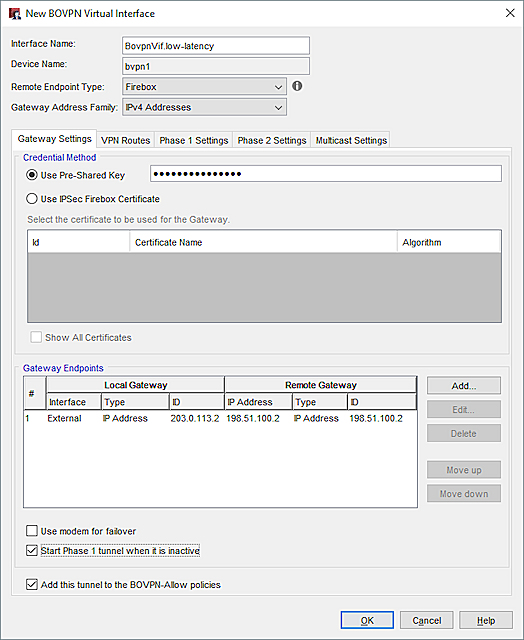
On the Firebox at Site A, specify these settings for the low-latency tunnel:
- Interface Name— In our example, we use the name BovpnVif.low-latency.
- Remote Endpoint Type — Firebox
- Gateway Address Family — IPv4 Addresses
- Credential Method — Use Pre-Shared Key
- Gateway Endpoints
- Interface — External
- Local Gateway— IP address of the External interface on this Firebox. In our example, we use 203.0.113.2.
- Remote Gateway— IP address of External-1 interface on the Site B Firebox. In our example, we use 198.51.100.2. This is the interface for the low-latency connection at Site B.
- VPN Routes tab — Specify virtual interface IP addresses, which you must do before you can add the BOVPN virtual interface to Link Monitor. The local IP address must match the peer IP address configured on the Site B Firebox. The peer IP address must match the local IP address configured on the Site B Firebox. Make sure the virtual interface IP addresses do not belong to any external or internal networks.

On the Firebox at Site A, specify these settings for the high-latency tunnel:
- Interface Name— In our example, we use the name BovpnVif.high-latency.
- Remote Endpoint Type — Firebox
- Gateway Address Family — IPv4 Addresses
- Credential Method — Use Pre-Shared Key
- Gateway Endpoints
- Interface — External
- Local Gateway— IP address of the External interface of this Firebox (203.0.113.2)).
- Remote Gateway— IP address of External-1 interface on the Site B Firebox. In our example, we use 192.0.2.2.
- VPN Routes tab — Specify virtual interface IP addresses, which you must do before you can add the BOVPN virtual interface to Link Monitor. The local IP address must match the peer IP address configured on the Site B Firebox. The peer IP address must match the local IP address configured on the Site B Firebox. Make sure the virtual interface IP addresses do not belong to any external or internal networks.


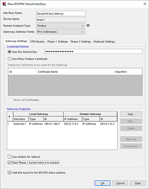
Specify these settings for the low-latency tunnel:
- Interface Name— BovpnVif.low-latency
- Remote Endpoint Type — Firebox
- Gateway Address Family — IPv4 Addresses
- Credential Method — Pre-Shared Key
- Gateway Endpoint
- Interface — External-1
- Local Gateway— IP address of the External-1 interface on this Firebox (198.51.100.2)
- Remote Gateway— IP address of the External interface on the Site A Firebox (203.0.113.2)
- VPN Routes tab — Specify virtual interface IP addresses. You cannot add the BOVPN virtual interface to Link Monitor unless you configure virtual IP addresses. The local IP address must match the peer IP address configured on the Site A Firebox. The peer IP address must match the local IP address configured on the Site A Firebox. Make sure the virtual interface IP addresses do not belong to any external or internal networks.

Specify these settings for the high-latency tunnel:
- Interface Name— BovpnVif.high-latency
- Remote Endpoint Type — Firebox
- Gateway Address Family — IPv4 Addresses
- Credential Method — Pre-Shared Key
- Gateway Endpoint
- Interface— External-2
- Local Gateway— IP address of the External-2 interface on the Site B Firebox (192.0.2.2).
- Remote Gateway— IP address of the External interface on the Site A Firebox (203.0.113.2).
- VPN Routes tab — Specify virtual interface IP addresses. You cannot add the BOVPN virtual interface to Link Monitor unless you configure virtual IP addresses. The local IP address must match the peer IP address configured on the Site A Firebox. The peer IP address must match the local IP address configured on the Site A Firebox. Make sure the virtual interface IP addresses do not belong to any external or internal networks.


We recommend that you add the external interfaces and BOVPN virtual interfaces to Link Monitor. To detect a logical link failure for an interface, the Firebox must be able to attempt communication with a Link Monitor target. Without a Link Monitor target, the Firebox detects a connection failure only after a physical disconnection, or if a valid IP address is not assigned to the interface (if the interface is dynamic).
To add BOVPN virtual interfaces to Link Monitor, your Firebox must have Fireware v12.4 or higher. When you add a BOVPN virtual interface to Link Monitor, the Firebox automatically adds a ping target to the IP address of the VPN peer. You cannot edit or remove this target.
For Site A, the Link Monitor configuration includes three interfaces:

For Site B, the Link Monitor configuration includes four interfaces:

If you cannot add a BOVPN virtual interface to Link Monitor, verify the BOVPN virtual interface configuration includes virtual interface IP addresses. For more information, go to Configure BOVPN Virtual Interface IP Addresses.
After you configure the BOVPN virtual interfaces, the two sites can add use static, dynamic, or SD-WAN routing to send traffic through either tunnel.
To make sure that VoIP traffic that originates from either network always uses the tunnel with lower latency:
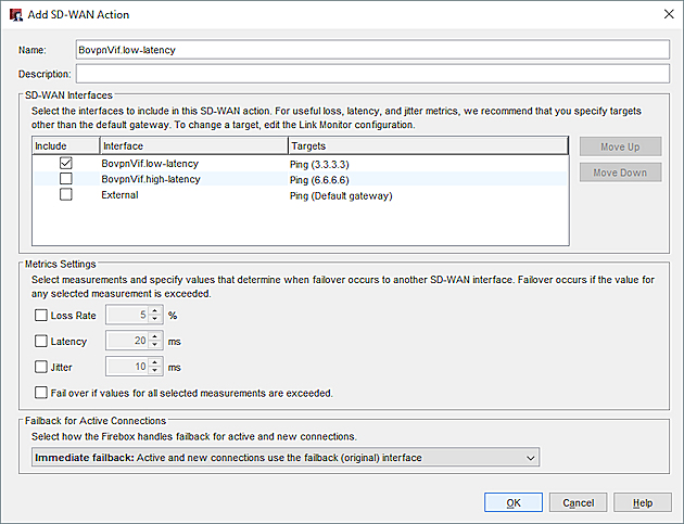
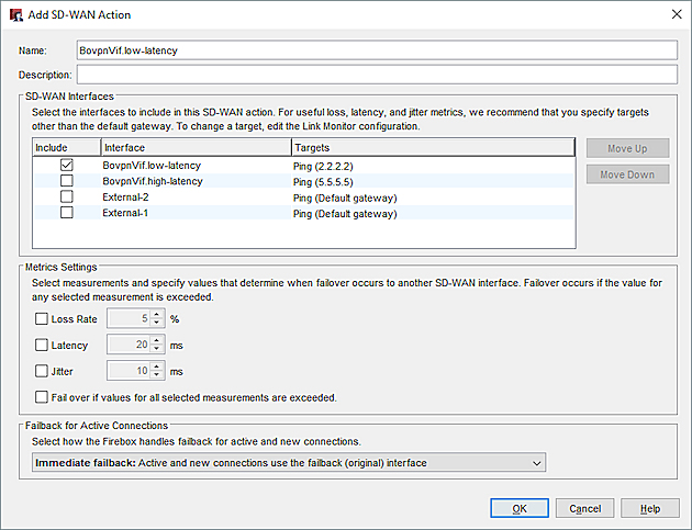
- Add an SD-WAN action that specifies the BovpnVif.low-latency virtual interface.
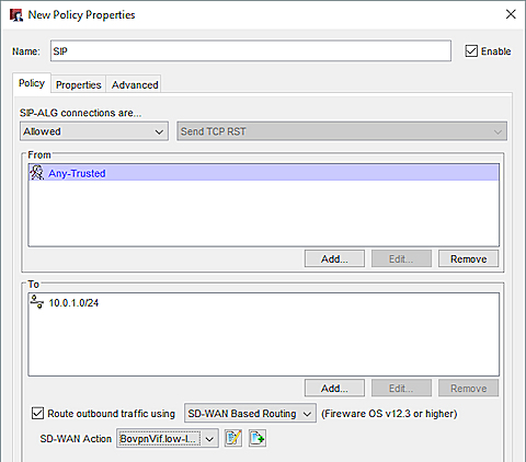
- In the SIP (VoIP) policy, specify the SD-WAN action that you added.
Add an SD-WAN Action (Site A)
The SD-WAN action specifies the BOVPN virtual interface that you added.
Add a VoIP Policy (Site A)
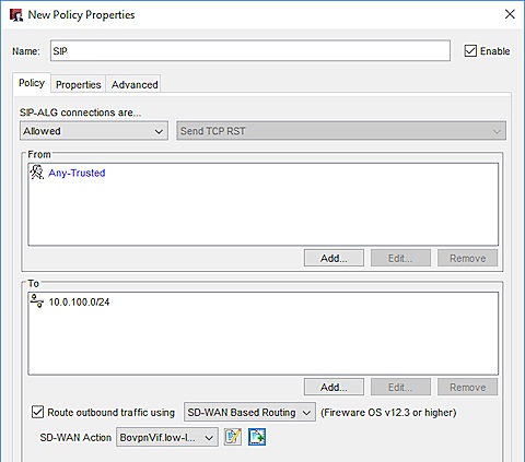
We recommend that you add a custom SIP packet filter policy.
The policy has these settings on the Site A Firebox:
- From — Any-Trusted. Or, specify the interface or local network where SIP traffic originates.
- To — The network IP address of the trusted network at Site B. In our example, we use 10.0.100.0/24.
- Route outbound traffic using — selected
- SD-WAN action — The name of the SD-WAN action you added. In our example, it is BovpnVif.low-latency.
Add an SD-WAN Action (Site B)
The SD-WAN action at Site B has the same settings as the SD-WAN action at Site A.
Add a SIP Policy (Site B)
We recommend that you add a custom SIP packet filter policy.
The policy at Site B has these settings:
- From — Any-Trusted. Or, specify the interface or local network where SIP traffic originates.
- To — The network IP address of the trusted network at Site A. In our example, we use 10.0.1.0/24.
- Route outbound traffic using — selected
- SD-WAN action — The name of the SD-WAN action you added. In our example, it is BovpnVif.low-latency.
Configure a BOVPN Virtual Interface