Configure Two VLANs on the Same Interface
A network interface on a Firebox is a member of more than one VLAN when the switch that connects to that interface carries traffic from more than one VLAN. This example shows how to connect one switch that is configured for two different VLANs to a single interface on the Firebox.
This diagram shows the configuration for this example.
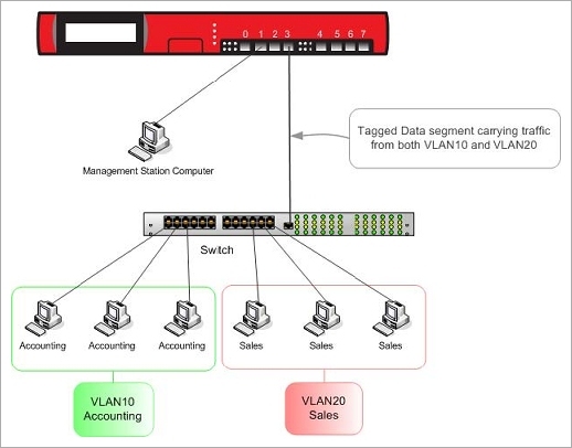
In this example, computers on both VLANs connect to the same 802.1Q switch, and the switch connects to interface 3 on the Firebox.
Each device on these two VLANs must set the IP address of the default gateway to be the IP address configured for the VLAN. In this example:
- Devices on VLAN10 must use 192.168.10.1 as their default gateway.
- Devices on VLAN20 must use 192.168.20.1 as their default gateway.
- Select Network > Interfaces.
- Select interface number 3.
- Click Edit.
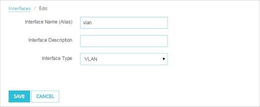
- In the Interface Name (Alias) text box type vlan.
- From the Interface Type drop-down list, select VLAN.
- Click Save.
- Select Network > VLAN.
- Click Add.
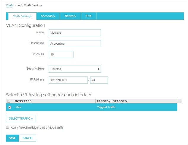
- In the Name text box, type a name for the VLAN. For this example, type VLAN10.
- In the Description text box, type a description. For this example, type Accounting.
- In the VLAN ID text box, type the VLAN number configured for the VLAN on the switch. For this example, type 10.
- From the Security Zone drop-down list, select the security zone. For this example, select Trusted.
- In the IP Address text box, type the IP address to use for the Firebox on this VLAN. For this example, type 192.168.10.1/24.
- In the interface list, select the interface called vlan.
- From the Select Traffic drop-down list, select Tagged traffic.
- Click Save.
- Click Add to add the second VLAN.
- In the Name text box, type VLAN20.
- In the Description text box, type Sales.
- In the VLAN ID text box, type 20.
- From the Security Zone drop-down list, select Optional.
- In the IP Address text box, type the IP address to use for the Firebox on this VLAN. For this example, type 192.168.20.1/24.
- In the interface list, select the interface called vlan.
- From the Select Traffic drop-down list, select Tagged traffic.
- Click Save.
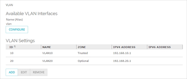
- Both VLANS now appear in the list, and are configured to use the defined VLAN interface.
Configure the VLAN Settings in Policy Manager
- Select Network > Configuration.
- Select the VLAN tab.
- Click Add.
The New VLAN Configuration dialog box appears. - In the Name (Alias) text box, type a name for the VLAN. For this example, type VLAN10.
- In the Description text box, type a description. For this example, type Accounting.
- In the VLAN ID text box, type the VLAN number configured for the VLAN on the switch. For this example, type 10.
- From the Security Zone drop-down list, select the security zone. For this example, select Trusted.
- In the IP Address text box, type the IP address to use for the Firebox on this VLAN. For this example, type 192.168.10.1/24.
- (Optional) To configure the Firebox to act as a DHCP server for the computers on VLAN10:
- Select Use DHCP Server.
- To the right of the Address Pool list, click Add.
- For this example, in the Starting address text box, type 192.168.10.10 and in the Ending address text box type 192.168.10.20.
The finished VLAN10 configuration for this example looks like:

- Click OK to add the new VLAN.
- Click Add to add the second VLAN.
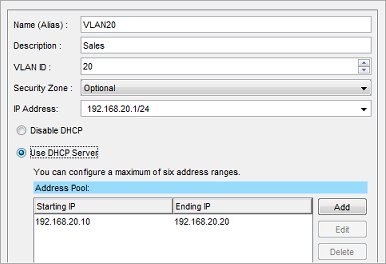
- In the Name (Alias) text box, type VLAN20.
- In the Description text box, type Sales.
- In the VLAN ID text box, type 20.
- From the Security Zone drop-down list, select Optional.
- In the IP Address field, type the IP address to use for the Firebox on this VLAN. For this example, type 192.168.20.1/24.
- (Optional) To configure the Firebox to act as a DHCP server for the computers on VLAN20:
- Select Use DHCP Server.
- To the right of the Address Pool list, click Add.
- For this example, in the Starting address text box, type 192.168.20.10 and in the Ending address text box type 192.168.20.20.
- Click OK to add the new VLAN.
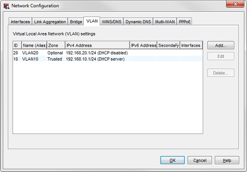
Both VLANs now appear in the VLAN tab of the Network Configuration dialog box.
- Click the Interfaces tab.
- Select Interface 3.
- Click Configure.
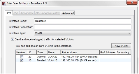
- From the Interface Type drop-down list, select VLAN.
- Select the Send and receive tagged traffic for selected VLANs check box.
- Select the check boxes for VLAN10 and VLAN20.
- Click OK.