Related Topics
Broadcast Routing Through a BOVPN Tunnel
This example shows how to configure the BOVPN tunnel to enable broadcast routing from a device at Site A to the IP addresses on the trusted network at Site B.
For this example, we assume the BOVPN tunnel has already been created between the two devices.
- For information about how to use Fireware Web UI to configure a BOVPN tunnel between two Fireboxes, see Set up a VPN Between Two Fireware Devices (Web UI).
- For information about how to use Policy Manager to configure a BOVPN tunnel between two Fireboxes, see Set up a VPN Between Two Fireware Devices (WSM).
For more information about the helper addresses used for broadcast routing, see Enable Broadcast Routing Through a Branch Office VPN Tunnel
Example Settings
These settings correspond to the settings shown in the screen shots used throughout this example.
SITE A (Firebox with Fireware v11.x or higher)
Trusted network IP address: 10.0.50.0/24
Existing tunnel: Tunnel_to_SiteB
Existing tunnel route: 10.0.50.0/24 <==> 192.168.100.0/24
SITE B (Firebox with Fireware v11.x or higher)
Trusted network IP address: 192.168.100.0/24
Existing tunnel: Tunnel_to_SiteA
Existing tunnel route: 192.168.100.0/24 <==> 10.0.50.0/24
Broadcast device at Site A
Network IP address: 10.0.50.3
Configure Broadcast Routing for the BOVPN Tunnel at Site A
First you must enable broadcast routing and configure the helper addresses for the BOVPN tunnel on the Site A device.
- Select VPN > Branch Office VPN.
- Select Tunnel_to_SiteB. Click Edit.
The Edit Tunnel dialog box appears. - From the Tunnel page, select the tunnel route and click Edit.
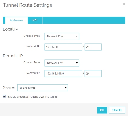
The Tunnel Route Settings dialog box appears.

- Click the Enable broadcast routing over the tunnel check box. Click OK.
You return to the Tunnel page. The Helper Addresses appear at the bottom of the Addresses tab.

- In the Helper Addresses section, type the IP addresses for each end of the broadcast tunnel. Use any two unused IP addresses, one for the local network and one for the remote network. You can set Local IP and Remote IP to any unused IP addresses. We recommend you use private IP addresses that are not used on any local network or on any remote network the Firebox connects to.
For this example:- Set the Local IP in the Site A configuration to 172.16.0.1.
- Set the Remote IP in the Site A tunnel configuration to 172.16.0.2.
- Save the configuration to the Firebox.
- Select VPN > Branch Office Tunnels.
The Branch Office IPSec Tunnels dialog box appears. - Select Tunnel_to_SiteB. Click Edit.
The Edit Tunnel dialog box appears. - From the Edit Tunnel dialog box, select the tunnel route and click Edit.
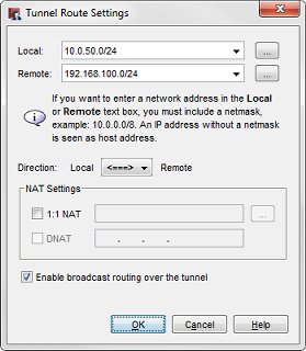
The Tunnel Route Settings dialog box appears.

- Click the Enable broadcast routing over the tunnel check box. Click OK.
You return to the Edit Tunnel dialog box. The Helper Addressees appear at the bottom of the Addresses tab.

- In the Helper Addresses section, type the IP addresses for each end of the broadcast tunnel. Use any two unused IP addresses, one for the local network and one for the remote network. You can set Local IP and Remote IP to any unused IP addresses. We recommend you use private IP addresses that are not used on any local network or on any remote network the Firebox connects to.
For this example:- Set the Local IP in the Site A configuration to 172.16.0.1.
- Set the Remote IP in the Site A tunnel configuration to 172.16.0.2.
- Save the configuration to the Firebox.
If you enable broadcast or multicast routing in more than one BOVPN tunnel, make sure that you use a different pair of helper IP addresses for each tunnel.
Configure Broadcast Routing for the BOVPN Tunnel at Site B
First you must enable broadcast routing and configure the opposite helper addresses for the BOVPN tunnel on the Site B device.
- Select VPN > Branch Office VPN.
- Select Tunnel_to_SiteA. Click Edit.
The Edit Tunnel dialog box appears. - From the Tunnel page, select the tunnel route and click Edit.
The Tunnel Route Settings dialog box appears. - Select the Enable broadcast routing over the tunnel check box. Click OK.
You return to the Tunnel page. The Helper Addressees appear at the bottom of the Addresses tab.

- In the Helper Addresses section type the IP addresses for each end of the multicast tunnel. These must be the same addresses you entered for the tunnel configuration in Site A, except that the order is reversed.
For this example:- Set the Local IP in the Site B tunnel configuration to 172.16.0.2
- Set the Remote IP in the Site B tunnel configuration to 172.16.0.1
- Save the configuration to the Firebox.
- Select VPN > Branch Office Tunnels.
The Branch Office IPSec Tunnels dialog box appears. - Select Tunnel_to_SiteA. Click Edit.
The Edit Tunnel dialog box appears. - From the Edit Tunnel dialog box, select the tunnel route and click Edit.
The Tunnel Route Settings dialog box appears. - Select the Enable broadcast routing over the tunnel check box. Click OK.
You return to the Edit Tunnel dialog box. The Helper Addressees appear at the bottom of the Addresses tab.

- In the Helper Addresses section type the IP addresses for each end of the multicast tunnel. These must be the same addresses you entered for the tunnel configuration in Site A, except that the order is reversed.
For this example:- Set the Local IP in the Site B tunnel configuration to 172.16.0.2
- Set the Remote IP in the Site B tunnel configuration to 172.16.0.1
- Save the configuration to the Firebox.
Broadcasts Routed Through the Tunnel
The BOVPN tunnel configured described in this example routes these broadcasts:
10.0.50.x/24 -> 192.168.100.255 (destination is the directed broadcast address of the remote network)
10.0.50.x/24 -> 255.255.255.255
192.168.100.x/24 -> 10.0.50.255 (destination is the directed broadcast address of the remote network)
192.168.100.x/24 -> 255.255.255.255
The BOVPN tunnel does not route these broadcasts:
0.0.0.0 -> 255.255.255.255 (dhcp/bootp broadcast)
10.0.50.x/24 -> 10.0.50.255 (netbios broadcast: not the directed broadcast address of the remote network)
192.168.100.x/24 -> 192.168.100.255 (netbios broadcast: not the directed broadcast address of the remote network)
203.0.113.x/24 -> 10.0.50.255 (source IP address does not match the local network)
198.51.100.x/24 -> 192.168.100.255 (source IP address does not match the local network)