Applies To: Cloud-managed Fireboxes, Locally-managed Fireboxes
On the Networks page, you can view the network list, DNS servers, wireless radios, SD-WAN list, ARP table, DHCP leases, and the routes that are configured on your Firebox.
This page is only available when your cloud-managed Firebox, or locally-managed Firebox with cloud reporting, is connected to WatchGuard Cloud.
To monitor networks on cloud-managed Fireboxes and locally-managed Fireboxes with cloud reporting:
- Select Monitor > Devices.
- Select a Firebox.
The Device Summary page for the selected Firebox opens. - Select Live Status > Networks.
The Networks page opens. The page refreshes automatically every 30 seconds.

Networks
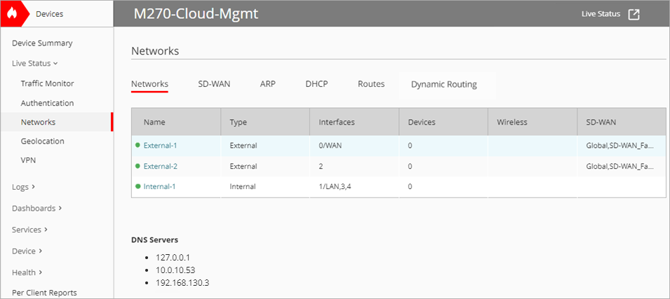
The Networks tab shows an overview of each network, including this information:
Name
The name of the network and the network status. A green icon indicates the network is up, and a red icon indicates the network is down. To view network details, click the name. For more information, see Network Details.
Type
The type of network (for example, Internal, External, or Guest).
Interfaces
The Firebox interface that enables the network connection.
Devices
The number of devices on the network.
Wireless
The SSID name if wireless is enabled for the network. The column is empty if wireless is disabled.
SD-WAN
All SD-WAN actions that include the network. Global indicates the Global Multi-WAN configuration includes the network.
The Networks tab also shows DNS servers and wireless radios (for Firebox wireless models).
SD-WAN and Global Multi-WAN
The SD-WAN tab shows all SD-WAN actions configured on the Firebox. This tab also shows the Global Multi-WAN configuration, which appears if you configure more than one external network.
SD-WAN
For each SD-WAN action, you can see this information:
SD-WAN Name and Overall Status
The name that you entered in the SD-WAN action configuration and an icon that indicates the overall status of the SD-WAN action.
The icon indicates the availability of networks in the SD-WAN action:
![]() — All networks in the SD-WAN action are active and qualified.
— All networks in the SD-WAN action are active and qualified.
![]() — Some networks in the SD-WAN action are not active or qualified.
— Some networks in the SD-WAN action are not active or qualified.
![]() — No networks in the SD-WAN action are active or qualified.
— No networks in the SD-WAN action are active or qualified.
A network is active when no physical link failure is detected, and if you enabled link monitoring, probes to the next hop are successful. A network is qualified if loss, latency, and jitter do not exceed the values that you entered.
Networks appear in the same order as in the SD-WAN action. The first interface is the primary interface. For the Failover SD-WAN method, the primary interface is preferred if it qualified.
Method
The SD-WAN method (Failover or Round-Robin).
Networks
The networks specified in the SD-WAN action. The icon color indicates the network status:
![]() The network is active and qualified.
The network is active and qualified.
![]() The network is not qualified.
The network is not qualified.
![]() The network is not active.
The network is not active.
For an SD-WAN action that uses the Round-Robin method, network icons include a percentage. The percentage indicates how traffic for this SD-WAN action is load balanced across all qualified networks in the SD-WAN action.
For an SD-WAN action that uses the Failover method, an arrow indicates that a network in the SD-WAN action failed over to another network in the SD-WAN action.
For information about how the Firebox handles inactive and unqualified networks, see About SD-WAN Methods.
To view details about each network in the SD-WAN action, click the tile. For more information, see SD-WAN Details.
Global Multi-WAN
For Global Multi-WAN, you can see this information:
Overall status
The Global Multi-WAN name, which is Global, and an icon that indicates the overall status of the Global Multi-WAN.
The icon indicates the availability of networks in the Global Multi-WAN:
![]() — All networks in the Global Multi-WAN are active.
— All networks in the Global Multi-WAN are active.
![]() — Some networks in the Global Multi-WAN are not active.
— Some networks in the Global Multi-WAN are not active.
![]() — No networks in the Global Multi-WAN are active.
— No networks in the Global Multi-WAN are active.
A network is active when no physical link failure is detected, and if you enabled link monitoring, probes to the next hop are successful.
Method
The method (Failover or Round-Robin).
Networks
The networks included in the Global Multi-WAN configuration.
Network icons
The icon color indicates the availability of networks in the Global Multi-WAN:
![]() and
and ![]() — The network is active.
— The network is active.
![]() and
and ![]() — The network is not active.
— The network is not active.
For the Failover Global Multi-WAN method, an arrow indicates that a network failed over to another network.
To view details about each network in the Global Multi-WAN configuration, click the tile. For more information, see SD-WAN Details.
Address Resolution Protocol Requests
Address Resolution Protocol (ARP) is a protocol that associates the IP address with the MAC address of a network device. This list shows a maximum of 25 ARP entries.

The ARP tab displays this information about the devices that have responded to an ARP request from the Firebox:
IP Address
The IP address of the computer that responds to the ARP request.
HW Type
The type of Ethernet connection that the IP address uses to connect.
Flags
If the hardware address of the IP resolves, it is marked as a complete ARP entry (0×2 ) or a complete static ARP entry (0×6). If the ARP entry is incomplete, the flag displays 0×0.
MAC Address
The MAC address of the network interface card that is associated with the IP address.
Interface
The interface on the Firebox where the hardware address for that IP address was found.
DHCP Leases
A DHCP lease is a temporary assignment of an IP address to a device on the network. This list shows a maximum of 25 DHCP entries.

The DHCP tab displays this information about the DHCP client leases for the Firebox:
Interface
The Firebox interface that the client is connected to.
IP Address
The IP address for the lease.
Host
The host name. If there is not an available host name, this is empty.
MAC Address
The MAC address of the network interface card that is associated with the IP address.
Start
The time when the client requested the lease.
End
The time when the lease expires.
Configured Routes
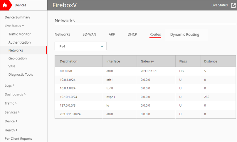
On the Routes tab, you can monitor the routes configured on your Firebox. From the drop-down list, select IPv4 or IPv6.
Live Status shows a maximum number of 1000 routes for the Firebox.

Destination
The destination IP address for the route.
Interface
The interface to which packets for this route will be sent (for example eth0 for interface 0).
Gateway
For an IPv4 route, the IP address of the gateway the route uses.
Flags
The flags set for each route. Some of the more common flags include:
- U indicates a route that is up
- H indicates a route to a host
- G indicates an IPv4 route that uses an external gateway or an IPv6 route that uses the next hop
Distance
The routing distance, which is the cost for the route. A lower number indicates a lower cost and higher route priority. The maximum value is 255.
In Fireware v12.9 or higher, the Distance setting replaces the Metric setting.
Configured Dynamic Routing
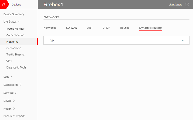
On the Dynamic Routing tab, you can monitor the dynamic routing that you enable on your cloud-managed Firebox. When you enable a dynamic routing protocol, the protocol routing status appears on this page. You can select a protocol to view its routing information and status.

The Routing Status window shows the routing information.

To refresh the information in the Routing Status window, click ![]() .
.
Add a Cloud-Managed Firebox to WatchGuard Cloud
Configure Firebox Network DHCP Settings
Add a Locally-Managed Firebox to WatchGuard Cloud